Phone and computer connection diagrams
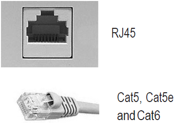
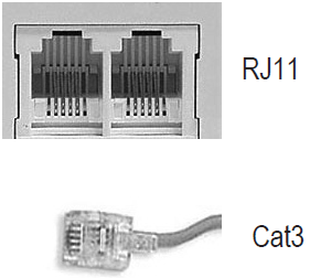
Regular telephone wire (Cat3) and (RJ11) jacks do not support VoIP services such as Lumen® Hosted VoIP or Lumen® SIP Trunking. Each workstation where you will be installing a VoIP phone must have Category 5 (Cat5), Category 5 Enhanced (Cat5E), or Category 6 (Cat6) cabling installed with an Ethernet (RJ45) jack. Cat6 cabling should be used where throughput of greater than 100Mbps is desired. You may work with Lumen, Lumen Professional Services, an electrician, or provider of your choice to install the cabling.
There are two components to your VoIP service:
- Internet Access: Lumen IQ® Networking, Dedicated Internet Access (DIA), or Metro Ethernet offer a variety of bandwidth and IP configurations to support the needs of your organization. The Lumen technician, as part of the install, will be installing a Lumen‑provided rental router/switch(s) if bundled, or for a fee, support the use of an existing customer‑provided approved router/switch. Consult with your Lumen representative to ensure the hardware has been certified for use on the Lumen network. The router/switch(s) will need adequate rack, wall, or shelf space in the location where the inside cabling terminates.
Lumen will extend the internet service/circuit within 10 feet of where the hardware is located as part of the request, but will not do the required inside wiring beyond that point, unless contracted to do so.
- Phone Installation: The phones will be shipped directly to your organization, along with any associated router/switch(s). Depending on the timing of the Internet service, you may receive more than one hardware delivery.
The Lumen technician will follow the appropriate installation scenario outlined below:
- Cat5/6 cabling must have a direct connection from the Ethernet jacks back to your patch panel or LAN switch for each phone. (This is also known as homerun cabling arrangement.)
- Each IP phone is shipped with one six foot Ethernet cord, which should be used to connect the computer to the phone or the phone to the Ethernet jack. (If your Ethernet jack is located farther than six feet from where the phone will be located, you will need to purchase longer Ethernet cords).
Supports VoIP
Doesn't support VoIP
Sample wiring scenarios
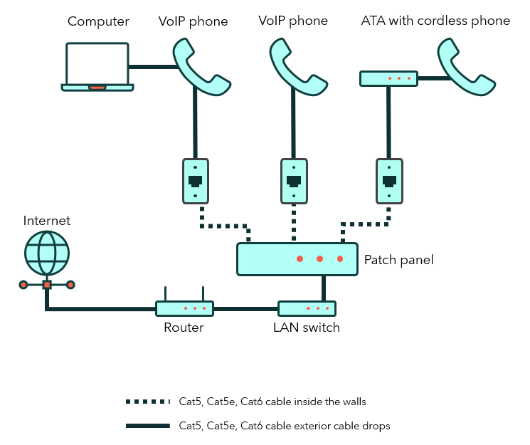
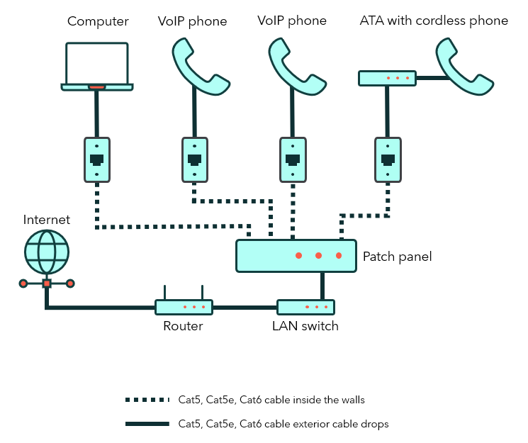
Scenario A
Single Cat5/6 drop at the desk: VoIP phones are co‑located with the computer and a patch panel.
- Plug the computer into the VoIP phone using the computer's Ethernet slot.
- Plug the VoIP phone Cat5/6 cable into an Ethernet jack.
- The Cat5/6 cable from the jack should already be connected to the patch panel. The diagram below illustrates cabling when there’s a patch panel in place.
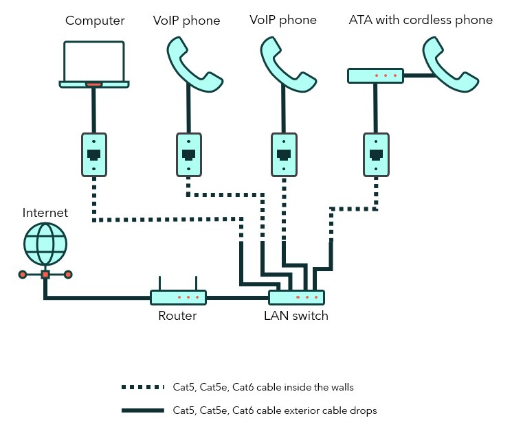
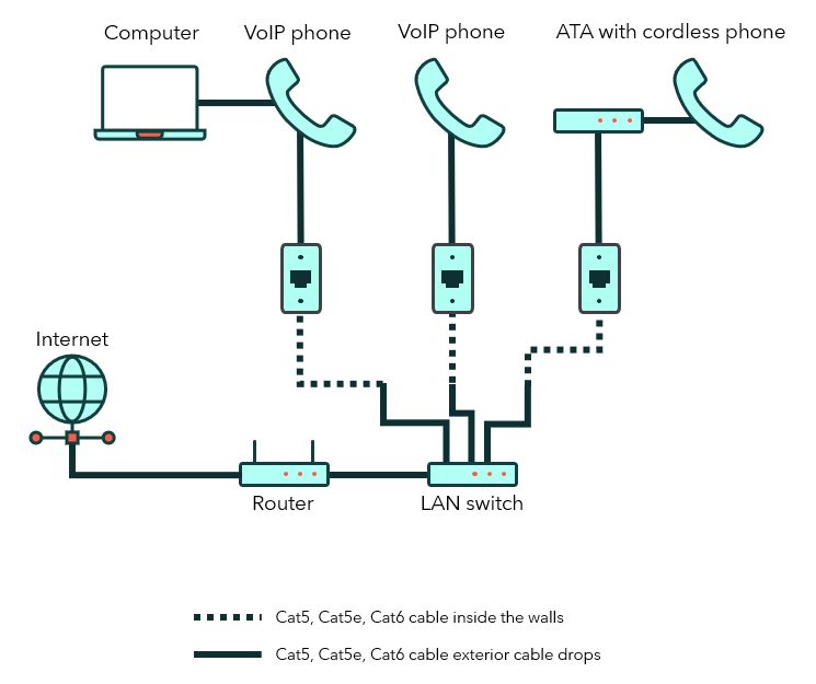
Scenario B
Single Cat5/6 drop at the desk: VoIP phones are co-located with the computer, no patch panel.
- Plug the computer into the VoIP phone using the PC Ethernet slot.
- Plug the VoIP phone Cat5/6 cable into an Ethernet jack.
- The Cat5/6 cable from the jacks plug directly into the switch (Ethernet ports). The diagram below illustrates cabling when there is no patch panel in place.
Scenario C
Two or more Cat5/6 cables at each seat location with a patch panel.
- Plug the computer into the Ethernet jack using Cat5/6 cable.
- Plug the VoIP phone into the Ethernet jack using Cat5/6 cable.
- Cat5/6 cable from the Ethernet jack should already be connected to the patch panel.
The diagram below illustrates cabling when there are two Cat5/6 or more cables installed at each location with a patch panel in place.
Scenario D
Two or more Cat5/6 cables at each seat location with no patch panel.
- Plug the computer into the Ethernet jack using Cat5/6 cable.
- Plug the VoIP phone into the Ethernet jack using Cat5/6 cable.
- Cat5/6 cable from the Ethernet jack will be plugged directly into your switch.
The diagram below illustrates cabling when there are two Cat5/6 or more cables installed at each location with no patch panel in place.