Network support: How traceroute works
Traceroute #8 shows an increase in latency at hop 3 but no latency after that. This is another common example of traceroute being misleading. Notice there’s no latency to the intended destination of 10.10.10.6. Ping #1 confirms this as well.
Ping #1
C:\Users\candres>ping 10.10.10.6
Pinging 10.10.10.6 with 32 bytes of data:
Reply from 10.10.10.6: bytes=32 time=4ms TTL=124
Reply from 10.10.10.6: bytes=32 time=4ms TTL=124
Reply from 10.10.10.6: bytes=32 time=4ms TTL=124
Reply from 10.10.10.6: bytes=32 time=3ms TTL=124
Ping statistics for 10.10.10.6:
Packets: Sent = 4, Received = 4, Lost = 0 (0% loss),
Approximate round trip times in milli-seconds:
Minimum = 3ms, Maximum = 4ms, Average = 3ms
Traceroute #8
C:\Users\candres>tracert 10.10.10.6
Tracing route to 10.10.10.6 over a maximum of 30 hops
1 1 ms 1 ms 1 ms SVL_FA0-0 [10.10.10.1]
2 1 ms 1 ms 1 ms SEA_Fa0-1 [192.168.1.2]
3 68 ms 319 ms 159 ms MIN_Fa0-0 [192.168.1.22]
4 4 ms 3 ms 3 ms OMH_Se0-1 [192.168.1.9]
5 6 ms 4 ms 4 ms 10.10.10.6
Trace complete.
There’s a clear discrepancy. Ping#1 between 10.10.10.2 and 10.10.10.6 shows no latency at all, traceroute #9 shows no latency between 10.10.10.6 and 10.10.10.2, yet traceroute #8 shows latency at hop 3. Why is this? To answer this we need to know the specific details of how traceroute operates which are shown below.
Traceroute #9 confirms no latency in the reverse path:
Traceroute #9
C:\>tracert 10.10.10.2
Tracing route to 10.10.10.2 over a maximum of 30 hops
1 3 ms 1 ms 1 ms OMH_Et0-0 [10.10.10.5]
2 3 ms 2 ms 2 ms TUL_Se0-1-0-0 [192.168.1.13]
3 5 ms 5 ms 5 ms PHX_Et1-1 [192.168.1.38]
4 5 ms 4 ms 4 ms SVL_Se0-0 [192.168.1.6]
5 4 ms 4 ms 4 ms 10.10.10.2
Trace complete
In this example we go over Traceroute #8
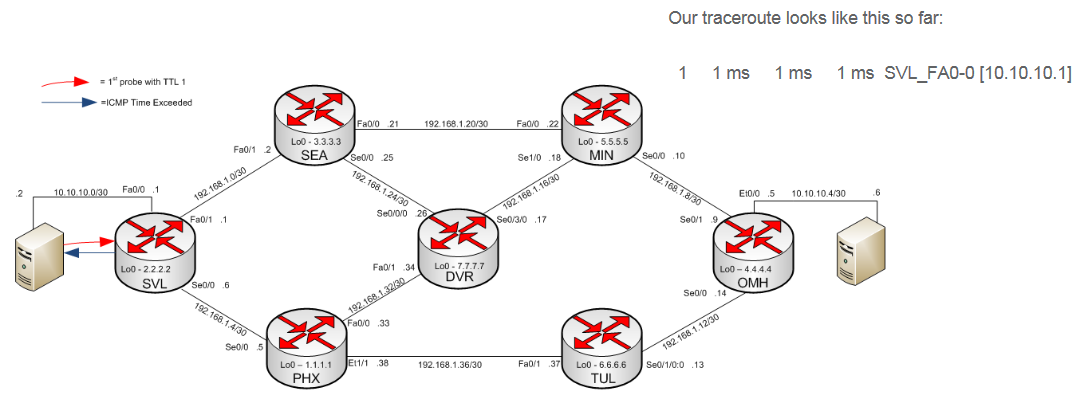
- The red arrow shows the start of the traceroute – as soon as the traceroute command is entered at 10.10.10.2 the host sends out an IP probe (either ICMP or UDP) with a TTL of 1. The packet enters the SVL router and the TTL is decremented to zero.
- Because the TTL is zero, SVL sends back an ICMP TTL exceeded message to the source of the probe packet (10.10.10.2). The ingress interface at SVL (Fa0/0 - 10.10.10.1) is used as the source IP address of the ICMP time exceeded message and therefore this IP shows up in Traceroute #8.
- Hosts/Routers will send out three probes for each “hop”. Three probes with TTL 1, three probes with TTL 2 and so on. This is why there are three different latency measurements for each hop. In the explanation, here we refer to each probe in succession (1st probe TTL 1, 2nd probe TTL 2, etc). Other tools like MTR and PingPlotter will send more than three probes.
Traceroute #8
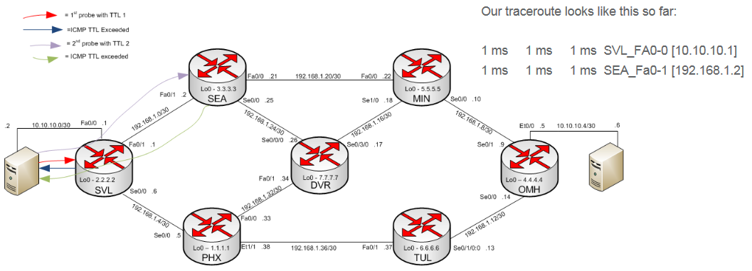
- After the ICMP TTL exceeded message is received at 10.10.10.2 the host sends out the 2nd probe with a TTL of 2.
- SVL receives the probe:
- Decrements the TTL to 1.
- Sends the probe to SEA.
- Decrements the TTL to 1.
- SEA receives the probe:
- Decrements the TTL to 0.
- Sends the ICMP TTL exceeded message to 10.10.10.2 with a source IP of 192.168.1.2 (Fa0/1). Now 192.168.1.2 shows up in the traceroute since it was the source IP of the TTL exceeded message.
- Decrements the TTL to 0.
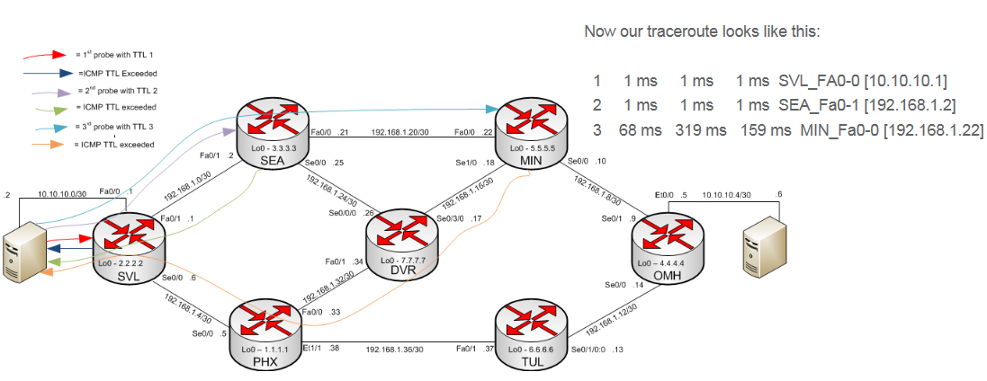
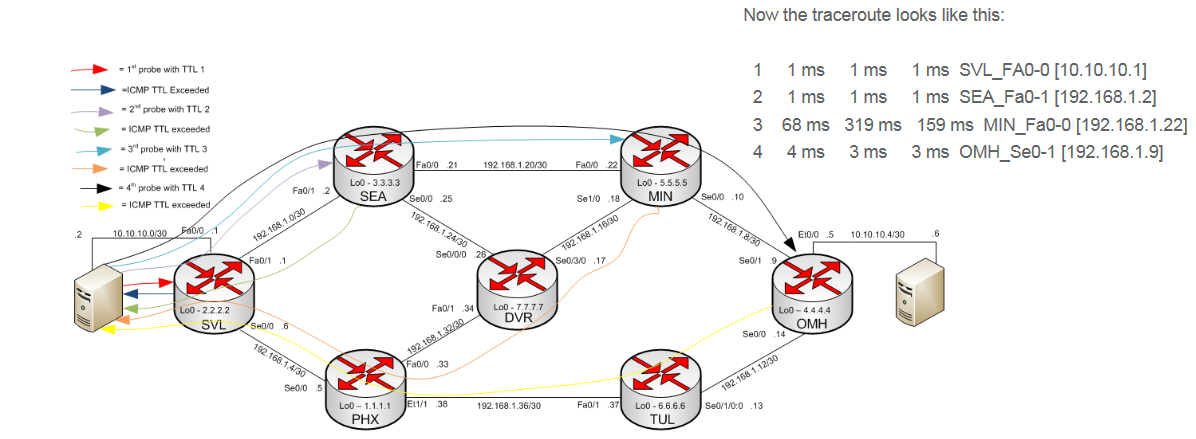
- When the host (10.10.10.2) receives the ICMP TTL exceeded message it sends out the 3rd probe with TTL 3.
- SVL receives the probe, decrements the TTL to 2 and forwards the packet to SEA.
- SEA receives the probe, decrements the TTL to 1 and forwards the probe to MIN.
- MIN receives the probe and decrements the TTL to 0. Since the TTL is at 0, it sends an ICMP TTL exceeded message back to 10.10.10.2 with a source IP of Fa0/0 (192.168.1.22).
Notice the path difference this particular ICMP TTL exceeded message takes. The first two used SVL and/or SEA while this most recent one goes through DVR and PHX.
- The host receives the ICMP TTL exceeded message and sends out the 4th probe with TTL 4.
- SVL receives the probe, decrements the TTL to 3 and forwards the probe to SEA
- SEA receives the probe, decrements the TTL to 2 and forwards the probe to MIN.
- MIN receives the probe, decrements the TTL to 1 and forwards the packet to OMH.
- OMH receives the probe, decrements the TTL to 0 and sends the TTL exceeded message back to the host (10.10.10.2) with its source IP of Se0/1 (192.168.1.9).
- The host receives the ICMP TTL exceeded message and sends out the 5th probe with TTL 5.
- SVL receives the probe, decrements the TTL to 4 and forwards the packet to SEA.
- SEA receives the probe, decrements the TTL to 3 and forwards the probe to MIN
- MIN receives the probe, decrements the TTL to 2 and forwards the probe to OMH.
- OMH receives the probe decrements the TTL to 1 and forwards the probe to 10.10.10.6.
- 10.10.10.6 receives the probe decrements the TTL to 0 and sends a reply back to the host (10.10.10.2) – In this case since the probes have been ICMP echo requests the far right host (10.10.10.6) sends back an ICMP echo reply, this is how the left host (10.10.10.2) knows to stop sending the probes, because it received an ICMP echo reply rather than an ICMP TTL exceeded message.
Some routers will send UDP probes rather than ICMP. These UDP probes will use a high destination port (> 30,000). The replies in that case will also be TTL exceeded messages at each hop with the final reply being an ICMP port unreachable message. The final hop in that case isn’t listening on the high port and this is the reason for the port unreachable message. This is the method for the router to know to stop sending probes as it receives the port unreachable message rather than the TTL exceeded message.
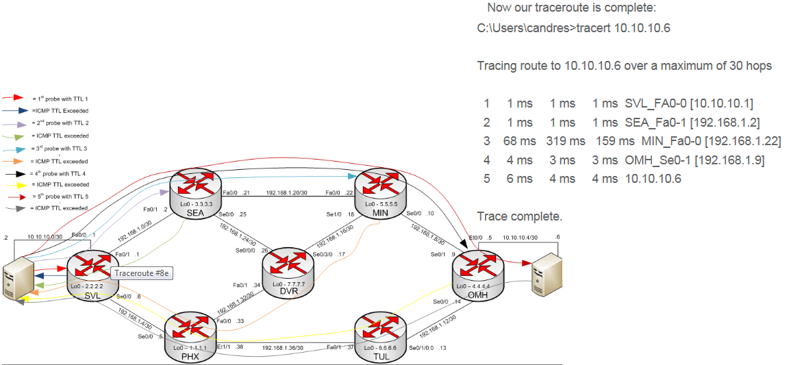
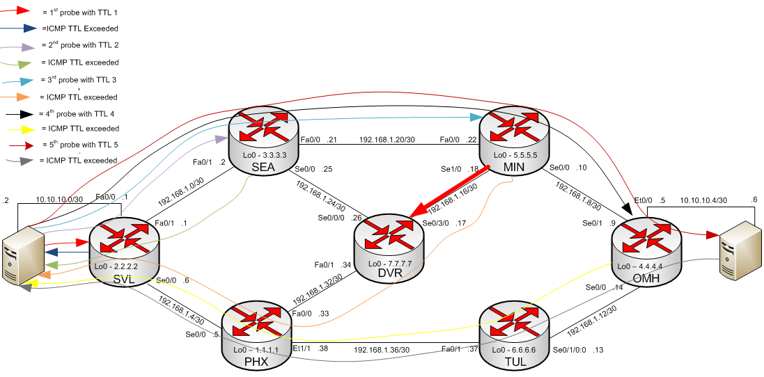
Looking at the diagram below, you can see why Traceroute #8 looks the way it does.
Out of all the probes and TTL exceeded messages the only packet to traverse the congested link, depicted with the bolded red arrow between MIN and DVR, is the TTL exceeded message generated by MIN. The rest of the packets traverse one or more links in the top (SVL > SEA > MIN > OMH) or bottom (OMH > TUL > PHX > SVL) paths.
For traceroute its possible for every packet, whether the probes or the TTL exceeded message, to take a path unique of the other traceroute packets. In the forward path for example probes may take different paths to reach the destination; this can happen if multipath is enabled for example. In the reverse path TTL exceeded messages can take different paths than the probes in asymmetric routing environments (the internet for example).
In this example the latency increase at hop 3 would not be a concern as it relates to performance between 10.10.10.2 and 10.10.10.6. This is because traffic between these two hosts never traverses the congested link (MIN > DVR). The forward path follows the top of the diagram (SVL > SEA > MIN > OMH) and the reverse path follows the bottom of the diagram (OMH > TUL > PHX > SVL).