Network support: Understanding the traceroute output
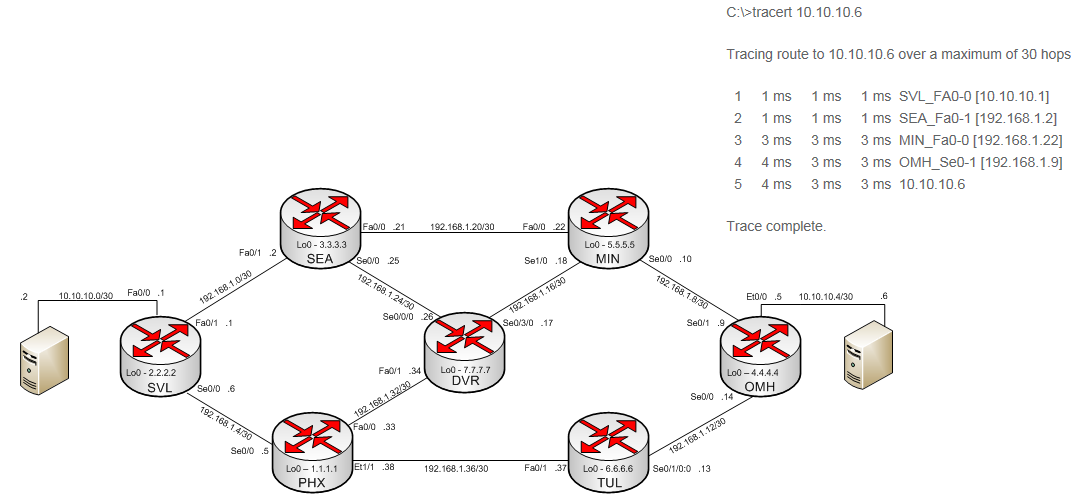
Traceroute #1 (below) shows a total of five hops; four devices or hops, in this case, are routers, with the fifth hop being the intended destination. (Note that it's common to see a traceroute complete, or reach its destination, even if the last hop isn’t the destination IP. This is because traceroute will often show the IP address of the ingress interface rather than the destination IP address.) Each hop in this traceroute is represented with an IP address (e.g., 10.10.10.1) and the resulting DNS lookup (e.g., SVL_FA0-0). In this example, the DNS records include an interface (FA-0-0) along with the hostname (SVL) of the router. You may not see the interface included in the DNS portion of a real-life traceroute; the decision on whether to include that is up to the owner of the IP. In these help topics, the interface names are included to make the traceroute easier to relate to the network diagram shown below and throughout these help topics. The DNS lookup will usually give some indication of what city, state, or area the device is located in. In the diagrams used throughout these help topics, we use the following abbreviations:
- SVL = Sunnyvale, CA
- MIN = Minneapolis, MN
- TUL = Tulsa, OK
- SEA = Seattle, WA
- OMH = Omaha, NE
- DVR = Denver, CO
- PHX = Phoenix, AZ
Each hop on Traceroute #1 shows three separate latency measurements, measured in milliseconds (ms), giving a rough idea of how much time it takes to traverse each hop; more on this later as this will become an important part in understanding traceroute.
Note: the traceroutes were taken in a lab environment, so this is why there isn’t higher latency; for instance, the latency for real-world transfers between Sunnyvale, CA and Omaha, NE would be larger than 3-4ms.
Traceroute #1